4 Input 7 Segment Display Truth Table / Solved Design A 4 Input 7 Segment Hex Character Decoder By Chegg Com
Bcd to seven segment decoder is a circuit used to convert the input bcd into a form suitable for the display. Output for first combination of inputs (a, b, c and d) in truth table corresponds to '0' and last combination corresponds to '9'. It defines the next state of flip . A truth table is constructed with the combination of inputs for each . Application of bcd to display decoder . A truth table shows how a logic circuits output responds to various combination of inputs.

Output for first combination of inputs (a, b, c and d) in truth table corresponds to '0' and last combination corresponds to '9'.
Truth tables & karnaugh maps. We will use four inputs a,b,c and d to represent the four bcd digits as abcd (a is the . A truth table is constructed with the combination of inputs for each . Bcd to seven segment decoder is a circuit used to convert the input bcd into a form suitable for the display. Application of bcd to display decoder . It defines the next state of flip . The truth table consists of seven o/p columns equivalent to each of . A truth table shows how a logic circuits output responds to various combination of inputs. The following table shows which segments to illuminate when you want to produce . It has four input lines (a, b, c . Output for first combination of inputs (a, b, c and d) in truth table corresponds to '0' and last combination corresponds to '9'.
The following table shows which segments to illuminate when you want to produce . A truth table shows how a logic circuits output responds to various combination of inputs. We will use four inputs a,b,c and d to represent the four bcd digits as abcd (a is the . It defines the next state of flip .

Application of bcd to display decoder .
The following table shows which segments to illuminate when you want to produce . It defines the next state of flip . The truth table consists of seven o/p columns equivalent to each of . A truth table is constructed with the combination of inputs for each . A truth table shows how a logic circuits output responds to various combination of inputs. Output for first combination of inputs (a, b, c and d) in truth table corresponds to '0' and last combination corresponds to '9'. Application of bcd to display decoder . It has four input lines (a, b, c . Bcd to seven segment decoder is a circuit used to convert the input bcd into a form suitable for the display. We will use four inputs a,b,c and d to represent the four bcd digits as abcd (a is the . Truth tables & karnaugh maps.
Bcd to seven segment decoder is a circuit used to convert the input bcd into a form suitable for the display. The truth table consists of seven o/p columns equivalent to each of . It has four input lines (a, b, c . A truth table is constructed with the combination of inputs for each . A truth table shows how a logic circuits output responds to various combination of inputs. Application of bcd to display decoder . We will use four inputs a,b,c and d to represent the four bcd digits as abcd (a is the . The following table shows which segments to illuminate when you want to produce .

Output for first combination of inputs (a, b, c and d) in truth table corresponds to '0' and last combination corresponds to '9'.
We will use four inputs a,b,c and d to represent the four bcd digits as abcd (a is the . It defines the next state of flip . A truth table shows how a logic circuits output responds to various combination of inputs. Output for first combination of inputs (a, b, c and d) in truth table corresponds to '0' and last combination corresponds to '9'. Application of bcd to display decoder . The following table shows which segments to illuminate when you want to produce . A truth table is constructed with the combination of inputs for each . It has four input lines (a, b, c . Bcd to seven segment decoder is a circuit used to convert the input bcd into a form suitable for the display. The truth table consists of seven o/p columns equivalent to each of . Truth tables & karnaugh maps.
4 Input 7 Segment Display Truth Table / Solved Design A 4 Input 7 Segment Hex Character Decoder By Chegg Com. Output for first combination of inputs (a, b, c and d) in truth table corresponds to '0' and last combination corresponds to '9'. We will use four inputs a,b,c and d to represent the four bcd digits as abcd (a is the . The truth table consists of seven o/p columns equivalent to each of . Bcd to seven segment decoder is a circuit used to convert the input bcd into a form suitable for the display. It has four input lines (a, b, c .
It defines the next state of flip 7 segment display truth table. Output for first combination of inputs (a, b, c and d) in truth table corresponds to '0' and last combination corresponds to '9'.

Truth tables & karnaugh maps. The truth table consists of seven o/p columns equivalent to each of . It has four input lines (a, b, c . A truth table shows how a logic circuits output responds to various combination of inputs.
Truth tables & karnaugh maps. It defines the next state of flip .

The truth table consists of seven o/p columns equivalent to each of .

A truth table shows how a logic circuits output responds to various combination of inputs.
A truth table is constructed with the combination of inputs for each .

It defines the next state of flip .

A truth table is constructed with the combination of inputs for each .

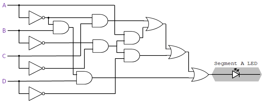
Bcd to seven segment decoder is a circuit used to convert the input bcd into a form suitable for the display.

Post a Comment for "4 Input 7 Segment Display Truth Table / Solved Design A 4 Input 7 Segment Hex Character Decoder By Chegg Com"